> For the complete documentation index, see [llms.txt](https://docs.protoboard.xyz/llms.txt). Markdown versions of documentation pages are available by appending `.md` to page URLs; this page is available as [Markdown](https://docs.protoboard.xyz/tutorials-and-examples/breadboard-from-blank-parts.md).

# Breadboard from Blank Parts

Create custom blank parts from scratch and wire an LED circuit on a breadboard.

## Goal

Build a simple LED + resistor circuit using **blank (custom) parts** you create yourself. By the end, you'll understand how to define parts from scratch, add domains and interfaces, place them on the canvas, wire them with a harness, and validate the result with DRC.

{% hint style="info" %}
**Time:** About 15 minutes. **What you need:** A free Protoboard account. No hardware required.
{% endhint %}

## Why blank parts?

The Protoboard parts library has hundreds of real-world components, but sometimes you need a part that isn't in the library yet. Blank parts let you model anything (a custom PCB, a passive component, or a prototype module) and still get the full benefit of Protoboard's validation engine.

In this tutorial you'll create two blank parts: an **LED** and a **220-ohm resistor**. These are common passive components that aren't individually cataloged in the library, making them a perfect use case for custom part creation.

***

## Steps

{% stepper %}
{% step %}

#### Create a new board

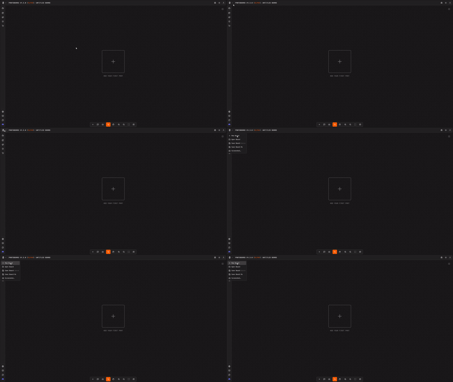
Open Protoboard and click the **Project menu** in the top-left corner of the top bar. Select **New Board**. Name it something like "LED Breadboard Circuit".

You'll land on an empty canvas, the infinite 2D workspace where you'll assemble your design.

<figure><img src="https://3535233690-files.gitbook.io/~/files/v0/b/gitbook-x-prod.appspot.com/o/spaces%2FHc6ZGiGpKHrs578383AS%2Fuploads%2Fgit-blob-5e076e506bed779d6dd2276c99d57a5e0bd4d816%2Ftut-create-new-board.gif?alt=media" alt="Opening the Project menu to create a new board"><figcaption><p>Project menu → New Board opens a fresh, empty canvas.</p></figcaption></figure>

{% hint style="success" %}
**Tip:** Keep board names descriptive. When you have multiple boards, a clear name saves you from opening the wrong one.
{% endhint %}
{% endstep %}

{% step %}

#### Create a blank part for the LED

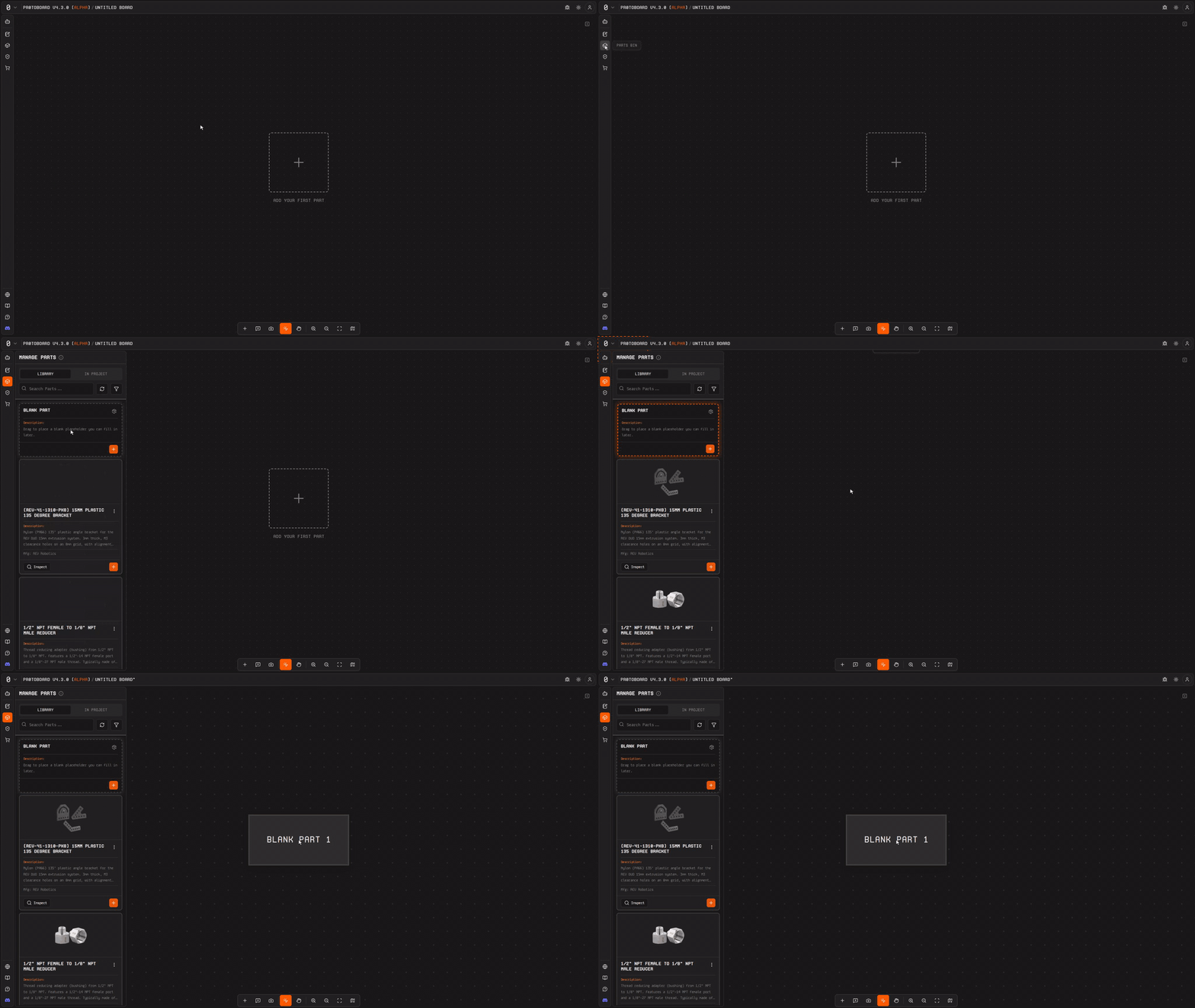
Open the **Parts Bin** by clicking the cuboid icon in the left sidebar. Instead of searching the library, select the option to create a **Blank Part**. A new empty part appears on your canvas.

<figure><img src="https://3535233690-files.gitbook.io/~/files/v0/b/gitbook-x-prod.appspot.com/o/spaces%2FHc6ZGiGpKHrs578383AS%2Fuploads%2Fgit-blob-e192efd8d2dcf162ae5baaefd2d6368bebf57c84%2Ftut-configure-blank-part.gif?alt=media" alt="Adding a Blank Part from the Parts Bin onto the canvas"><figcaption><p>Parts Bin → Blank Part lands an empty part on the canvas, ready to configure in the Inspector.</p></figcaption></figure>

Select the part and open the **Inspector** panel on the right. Configure the following:

1. **Name:** Set it to `LED (Red)`
2. **Description:** `Standard 5mm red LED, forward voltage ~2V, max 20mA`
3. **Domain:** Add the **Electrical** domain
4. **Interface:** Add a **power input** interface with the role set to **return** (the LED consumes power). This interface should include two functions:
   * `Anode`: signal class: power, direction: sink
   * `Cathode`: signal class: ground, direction: sink

{% hint style="warning" %}
**Don't skip the interface.** A part without at least one interface has no connection points, so it can't participate in harnesses or DRC validation.
{% endhint %}
{% endstep %}

{% step %}

#### Create a blank part for the 220-ohm resistor

Create another **Blank Part** from the Parts Bin. Select it and configure in the Inspector:

1. **Name:** Set it to `220-ohm Resistor`
2. **Description:** `220-ohm through-hole resistor for current limiting`
3. **Domain:** Add the **Electrical** domain
4. **Interface:** Add a **pass-through** interface with two functions:
   * `Terminal A`: signal class: power, direction: bidirectional
   * `Terminal B`: signal class: power, direction: bidirectional

The resistor acts as a pass-through element: current flows in one terminal and out the other. This is different from the LED, which has a defined polarity (anode/cathode).
{% endstep %}

{% step %}

#### Arrange both parts on the canvas

You should now have two parts on the canvas: the LED and the resistor. Drag them so they're near each other with some space between them; this gives you room for the harness connection line.

{% hint style="info" %}
**Layout tip:** The canvas supports snap-to-grid. Keeping parts aligned makes your board easier to read and share.
{% endhint %}
{% endstep %}

{% step %}

#### Create a harness between the resistor and the LED

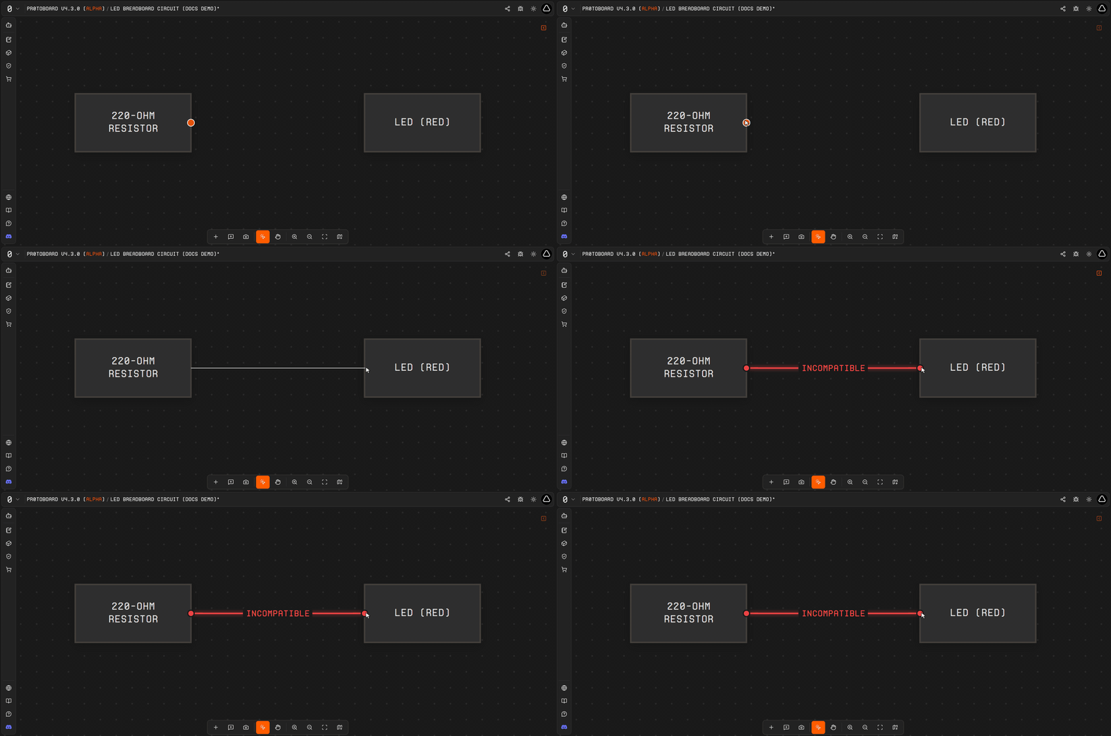
<figure><img src="https://3535233690-files.gitbook.io/~/files/v0/b/gitbook-x-prod.appspot.com/o/spaces%2FHc6ZGiGpKHrs578383AS%2Fuploads%2Fgit-blob-2f65234b6662db51ae5690696088bf80d94770c0%2Ftut-create-harness.gif?alt=media" alt="dragging from the resistor toward the LED to create a harness"><figcaption><p>Show the drag gesture from the resistor to the LED, with the harness appearing on release.</p></figcaption></figure>

Hover near the edge of the **220-ohm Resistor** part until a **connection handle** appears on the edge. Click and drag from that handle toward the **LED** to create a **harness**.

What you'll see next depends on whether you configured interfaces in Steps 2 and 3:

{% tabs %}
{% tab title="With interfaces configured (Steps 2–3 complete)" %}
Protoboard auto-detects the compatible pair and the harness appears with a **PARTIALLY\_CONFIGURED** or **CONFIGURED** label. Open the Inspector on the harness to review the proposed **interface link** pairing the resistor's pass-through interface with the LED's power input interface.
{% endtab %}

{% tab title="Without interfaces yet (skipped Steps 2–3)" %}
The harness still appears, but it's flagged **INCOMPATIBLE** in red (see the GIF above). There's nothing for Protoboard to match because the parts have no interfaces yet. Go back to Steps 2 and 3 to configure the interfaces on each part, then re-draw the harness.
{% endtab %}

{% tab title="If auto-detect doesn" %}
If the interfaces are configured but don't auto-match (can happen with very generic definitions), create the interface link manually. Select the harness, open the Inspector, and use the link editor to pair the resistor's Terminal B with the LED's Anode.
{% endtab %}
{% endtabs %}
{% endstep %}

{% step %}

#### Link the interfaces and assign functions

With the harness selected, open the **Inspector** and look at the interface link detail view. You need to create **function links** that map individual signals between the two parts:

* Map the resistor's **Terminal B** to the LED's **Anode**
* Map a shared **ground reference** to the LED's **Cathode**

This tells Protoboard exactly how current flows: through the resistor, into the LED anode, and out through the cathode to ground.
{% endstep %}

{% step %}

#### Run the Design Rule Check (DRC)

Click the **Board Review** icon (shield icon) in the left sidebar to open the validation panel and run DRC.

If everything is set up correctly, you should see:

* **CONFIGURED** (green) on the harness between the resistor and the LED

{% hint style="success" %}
**All green?** Your circuit is valid. The resistor is properly connected in series with the LED, current-limiting the circuit as intended.
{% endhint %}

If you see issues, here's what they mean:

| DRC state                         | What it means                                         | How to fix                                                        |
| --------------------------------- | ----------------------------------------------------- | ----------------------------------------------------------------- |
| **PARTIALLY\_CONFIGURED** (amber) | Some function links are missing                       | Open the harness in Inspector and assign the unmapped functions   |
| **NOT\_CONFIGURED** (red)         | The interface link exists but no functions are mapped | You need to create function links (Step 6)                        |
| **INCOMPATIBLE** (red)            | The interfaces can't connect                          | Check that roles are complementary (output/pass-through to input) |
| {% endstep %}                     |                                                       |                                                                   |
| {% endstepper %}                  |                                                       |                                                                   |

***

## What you just learned

| Concept          | What it means                                                                           |
| ---------------- | --------------------------------------------------------------------------------------- |
| **Blank part**   | A custom component you define from scratch when the library doesn't have what you need  |
| **Domain**       | The system category a part belongs to (Electrical, Mechanical, Pneumatic, etc.)         |
| **Interface**    | A connection point on a part that other parts can link to                               |
| **Function**     | An individual signal or pin within an interface (like Anode, Cathode, SCL, SDA)         |
| **Pass-through** | An interface role for components that pass signals through (like resistors, connectors) |

***

## Common failures

<details>

<summary>My blank part doesn't show up as connectable</summary>

Make sure you added at least one **interface** with a valid protocol type and role. Parts without interfaces have no connection points for harnesses. Go back to the Inspector and add an electrical interface.

</details>

<details>

<summary>DRC shows NOT_CONFIGURED even though I created a harness</summary>

Creating a harness is just the first step. You also need to create **function links** inside the interface link. Select the harness, open the Inspector, and map the individual functions (terminals/pins) between the two parts.

</details>

<details>

<summary>I want to add a power source but there's no battery in the library for this</summary>

Create another blank part for your power source (e.g., a 5V USB power supply or a coin cell battery). Give it an electrical domain with a power output interface. Then create a harness from the power source to the resistor's Terminal A.

</details>

<details>

<summary>Can I reuse these blank parts in other boards?</summary>

Yes. Blank parts are saved as **templates** within your project. You can clone them or export the template for use in other boards. Over time, frequently used custom parts become your personal library.

</details>

***

## Next steps

* [**MCU + Sensor + Regulator**](/tutorials-and-examples/mcu-sensor-regulator.md): Build a real system using library parts (Arduino Uno Rev3 + BME280 + MCP16251T)
* [**Parts: Add / Edit / Custom**](/user-guide/parts-add-edit-custom.md): Deep dive into part creation and template management
* [**Connections & Compatibility**](/user-guide/connections-and-compatibility.md): Understand how Protoboard decides which parts can connect


---

# Agent Instructions
This documentation is published with GitBook. GitBook is the documentation platform designed so that both humans and AI agents can read, navigate, and reason over technical content effectively. Learn more at gitbook.com.

## Querying This Documentation
If you need additional information that is not directly available in this page, you can query the documentation dynamically by asking a question.

Perform an HTTP GET request on the current page URL with the `ask` query parameter, and the optional `goal` query parameter:

```
GET https://docs.protoboard.xyz/tutorials-and-examples/breadboard-from-blank-parts.md?ask=<question>&goal=<endgoal>
```

`ask` is the immediate question: it should be specific, self-contained, and written in natural language.
`goal` is optional and describes the broader end goal you are ultimately trying to accomplish on behalf of the user. GitBook uses it to tailor the answer towards what is most useful for that goal.

The response will contain a direct answer to the question and relevant excerpts and sources from the documentation.

Use this mechanism when the answer is not explicitly present in the current page, you need clarification or additional context, or you want to retrieve related documentation sections.